Features
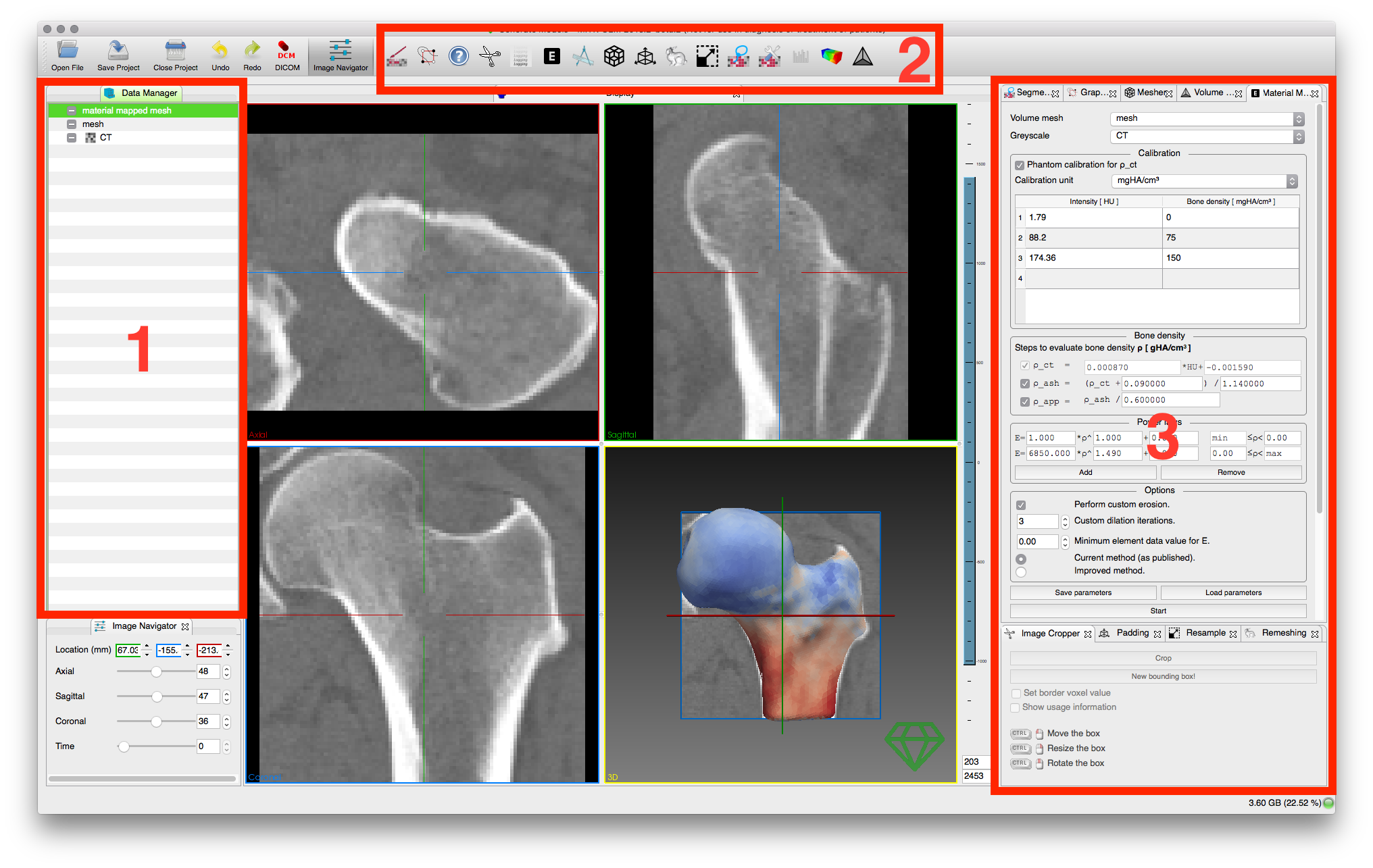
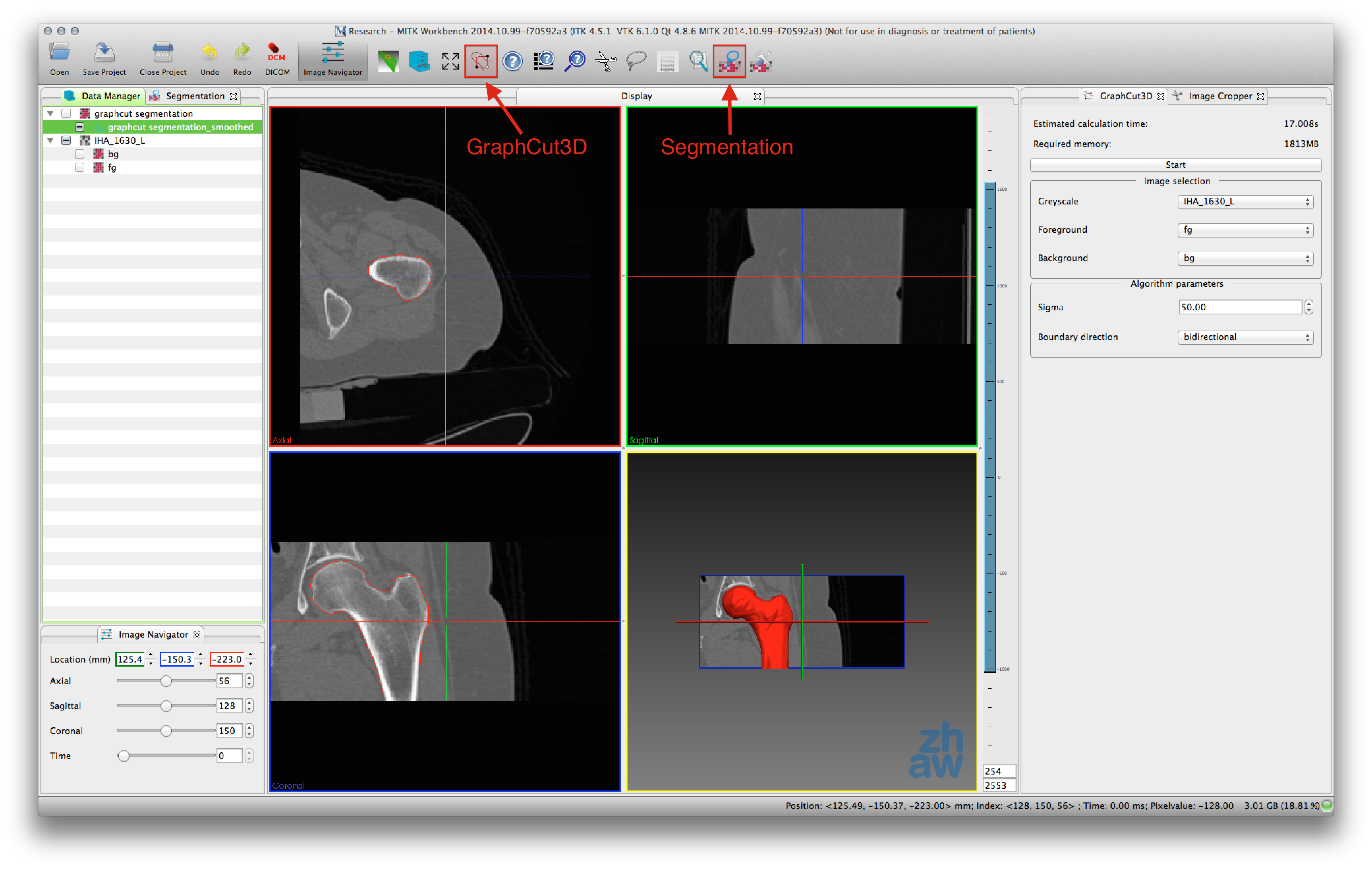
MITK-GEM implements all its features as plugins for the Medical Imaging Interaction Toolkit (MITK) Workbench. It expands the MITK Workbench by offering a finite element model generation workflow with the following steps:
- Interactive image segmentation with 3D Graphcuts
 .
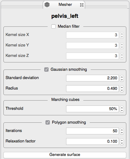
. - Surface mesh generation
 .
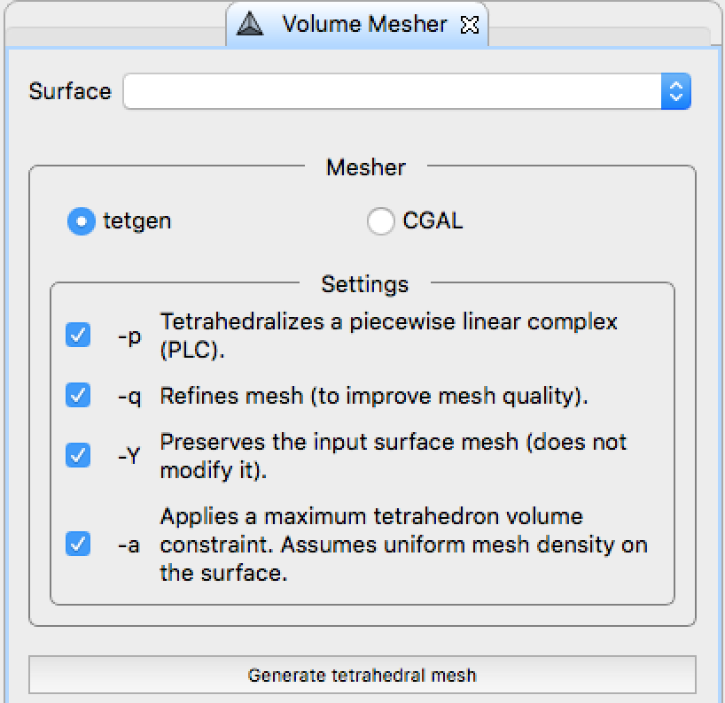
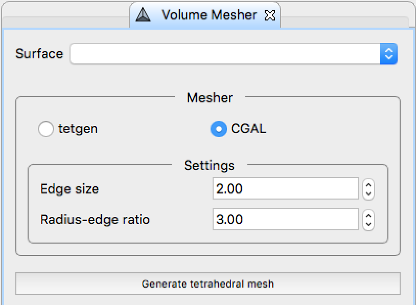
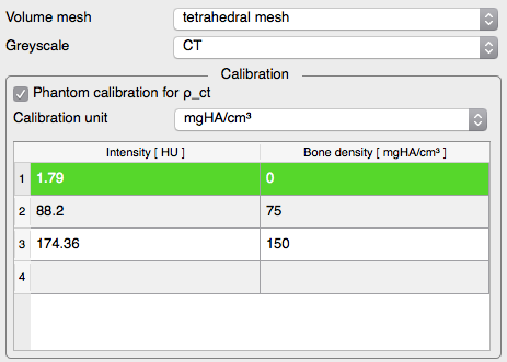
. - Tetrahedral mesh generation
 .
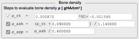
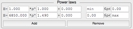
. - Highly configurable material mapping procedure
 .
.
The complete workflow going from MITK-GEM to Ansys is demonstrated by extracting the proximal femur from a CT image and simulating a sideways fall.